powerswitch
2000-07-17
Here we go! i finally managed to build a upwards switching power regulator
that finally has some output power ;)
My former designs never did a good job. They took several minutes
to make 30 Volts of output voltage from a 10 Volts supply. And when you started
to put a load on the output, the circuit broke down.
but this is history!
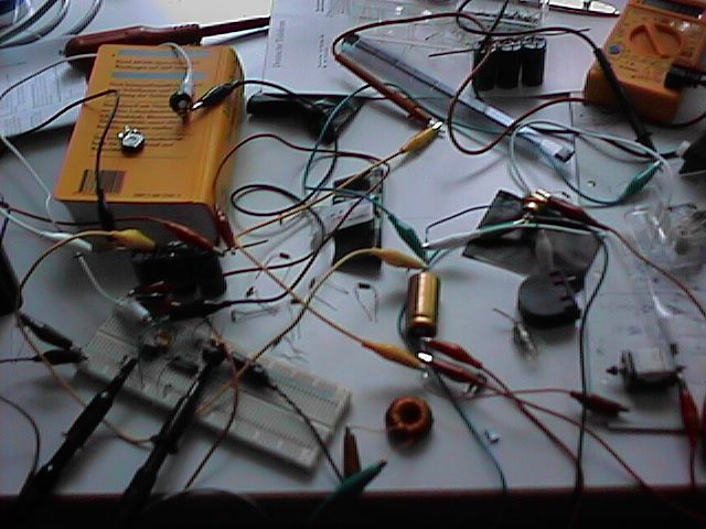
Here you see the overall circuitry. On the left below the yellow book there
are three condensators. They are stabilizing input voltage. On the breadboard
you have a NE555 timer to create square wave output. It feeds its output
into a LM324 operational amplifier to put more power behind it ;)
The output of the op-amp drives a BUK100-A Mosfet transistor.
there is a copper coil in the center bottom of the image. it is connected
to positiv power supply. the other end is connected to a diode (the golden one)
and the diode is connected to the output condensator (the golden one).
The transistor pulls the point between the diode and the coil to zero, or
leaves it where it is. That's the most simple up-switching design i know of.
Oh by the way you see a electric engine in the right low part of the image.
it is of a old model railroad i once had. I still can't believe it really
rotates :)
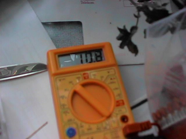
Now ain't that fantastic output voltage???
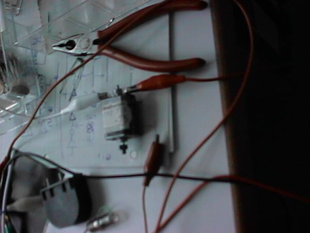
the engine again.
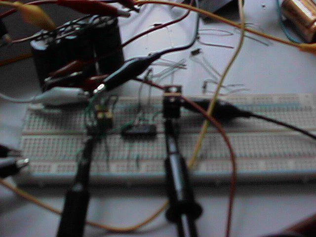
the breadboard. on the left the ne555 with two yellow condensators.
in the middle the op-amp. on the right two parallel BUK-100A.
i found out two work better than one :)
you see the oscillator probes connected here.
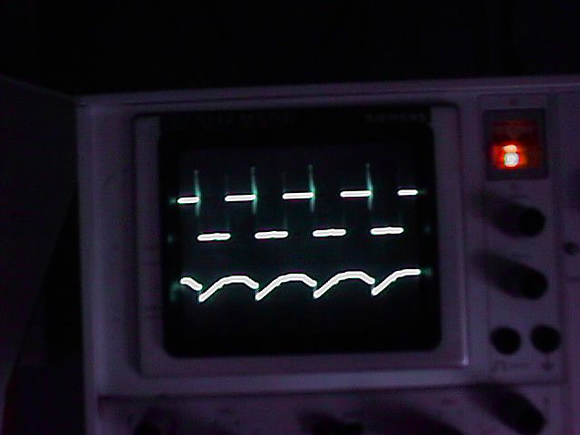
two channel oscillogram. the top one shows output of the ne555. i don't know
why there are spikes. i thought that sucking coil would be far away from this
circuit, but i am probably wrong. anyway the spikes seem not too bad :)
the lower channel shows the Gate of the transistor. as you see it goes from
low to high and back. the op-amp could be a little more powerful though.
i'd like to have this wave rectangular, but hey it works!
now let's tell you about the wonderful characteristics of this device:
Input: 6 Volts DC 0.8 Amps = 4.8 Watts
Output: 10.2 Volts DC 0.17 Amps = 1.73 Watts
That means the device has eta=36%
If you are a electronic brain you should know that it works much better,
but i am just happy that the circuit even works!
by the way. the device has no shutdown
this means if you don't connect output load, the output voltage will VERY
quickly (i tested) reach 40 Volts. this is critical, because the output
condensator explodes if it surpasses 40 Volts. Of course a real application
would need additional shutdown.
oh i did another test:
Input: 4.7 Volts DC 0.64 Amps = 3 Watts
Output: 9.5 Volts DC 0.15 Amps = 1.42 Watts
That means eta=47%
What an improvement :) i did this by reducing frequencies. still i think
the optimal solution would be to control the coil by a schmitt trigger.
mmmh maybe i should try that. we'll see.
| (erikyyy at erikyyy dot de, Erik Thiele) |
back |