CONTENTS
| 1. | Why this FAQ |
| 2. | Would it be possible for you to send me a list of parts so, I can try to build my own eycar? |
| 3. | Wouldn't you please please please translate everything into english? |
| 4. | Where does the EYCar get it's energy from? |
| 5. | Please tell me more about your radio data transmission system |
| 6. | How did you control the motors? |
| 7. | Tell me more about the sensoric system. |
| 8. | Are any of the circuts you used available in Postscript format? Any format? |
| 9. | I bought your stupid TCA3727. what now ? |
| 10. | I installed all this radio stuff, but it just DOESN'T WORK! |
1. Why this FAQ
I wrote this FAQ, because people asked me the same questions again and again. If I have to write the same things again and again, quality will suffer, so I wrote this FAQ, and I am still maintaining and extending it. (See the Version number on top of the file) Please do not be angry, if I answer your emails with this FAQ! Remember: this impersonal way of communication gives you more information, than a personal answer. If your question isn't answered in this FAQ, tell me! I will extend the FAQ, or just answer. I WILL answer your questions! Do not think i hate you, only because of the short email answers I will now create!
2. Would it be possible for you to send me a list of parts so, I can try to build my own eycar?
Hmmmm :-) The "History of development - detailed" section is showing the development process. Unfortunately this is in german. There are many pictures, though. Just click on EVERY date and look at the pictures... I know that this is no "list of parts" or a EYCar-building-HOWTO. Even the german reading people won't be able to understand everything, because this just isn't a building instruction :) Please ask me more concrete questions, I will then include them into the FAQ.
3. Wouldn't you please please please translate everything into english?
I am too lazy. please ask me questions about concrete problems, and I will include the answers in this FAQ.
4. Where does the EYCar get it's energy from?
A NORMAL computer mainboard needs +12V, -12V, +5V, -5V, 0V. The voltages should be constant! So the direct connection of a battery to the mainboard is like murder. (but I did it anyway ;) If you are lucky, your mainboard is a "good" mainboard and it doesn't die of the batteries 6,3V or so. I used lead acid batteries. They provide much amperes, and it takes a long time, until their power is down at 5V. If it gets lower, the computer does errors, NMIs and suddenly it enters a RESET-loop :) at least mine did. DANGER! using too high voltages causes Network cards to fail... your computer may even explode :-) This is your own risk. I still think I was the most stupid guy on earth. DO NOT DIRECTLY CONNECT ANY KIND OF BATTERY TO YOUR MAINBOARD! Next problem. How to generate the negative voltages? (-12V, -5V). Well at first I found out, that none of my hardware needed -5V, so I left it away. Just do not connect it on your mainboard, and all is OK. But RS232 needs -12V! So i bought some cheap niccel cadmium 12V accumulators and connected them to the -12V. This is waste! (I now know) There exist cheap chips, that convert 12V to -12V! Use them instead of my stupid approach. otherwise you waste unnecessary money. (the chips do not provide extreme amounts of amperes, but your mainboard needs very low current on -12V.) Now, how should you create 12V and 5V ? Use low-drop voltage regulators. You need to be an electronic man ;) to understand this. (i am none. so please don't ask me, HOW to do this) Please do this and do not directly connect batteries to your mainboard. Next problem. Your mainboard has a "power good" signal. i just didn't connect it. :) if this doesn't work, use a normal power supply and look what it does with the power good signal. you will probably find out, that "power good" is a digital signal of either 0V or 5V (i hope) You will then find out, wich of the two means "power good". now just connect (please insert a 1 kilo ohms resistor) the signal to your 0V or 5V power supply. this is the easiest. should work. now this was everything I know about this problem. My solution was NO good, so please ask anyone else :) I know that there exist expensive solutions that convert any kind of bullshit voltage input into nice +12,-12,+5,-5 output. specially for computers.
5. Please tell me more about your radio data transmission system
Hardware, please remember: the car is finished! I ain't got no problems left with my hardware, even if this outdated page sais so.
6. How did you control the motors?
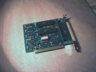
The motors are stepper engines. cheapest motors are used. 10 deutschmarks only. their control is done via Siemens TCA 3727. this is a very little chip. it does exactly the RIGHT thing :-) it doesnt cost more than a few Deutschmarks. the data sheet of the chip tells you everything. VERY easy. you needn't be an electronics engineer, definitly not. the chip has some digital inputs. therefore i used a card from a firm called ComputerBoards Inc. or something like that. This is a photo of it Everything is cheap and easy. And it is as perfect as expensive stepper engine control boards, BUT your computer has to be able to control the chip in REALTIME! This is one of the many reasons, why i used RealTime Linux. (RT Linux). So, if you want to do this yourself, buy the Siemens chip, and a cheap BIPOLAR stepper engine. you can control the chip via parallel port of your computer. if you have too many engines, the pins of your parallel IO port are not enough, and you should consider buying a digital TTL IO card.
7. Tell me more about the sensoric system.
First, feel ashamed, that you didn't notice this and that URL ;). The laser beam can be switched on and off. This is really trivial. a TTL output controls a transistor, that controls the beam. the returning beam is noticed via a foto-transistor. it is put through an operation amplifier (OP) and the result goes into a IRQ channel of the computer. the next is RT-Linux's and my software's job, and hell of mathematics :-) This is really complicated and you will probably get frustrated with this thing, so think TWICE, before you decide to get this complicated way of position determining working. But, IF you REALLY get it working, TELL me :-) i will be very happy. and of course i'll try to tell you about situations where your algorithm fails, and mine succeeds. btw. it is no secret. you can download my code, and you can also read the algorithm description. (german)
8. Are any of the circuts you used available in Postscript format? Any format?
No. but see 6. if you think about the motors.
9. I bought your stupid TCA3727. what now ?
sorry this is german (as you can see)
parallele schnittstelle hat TTL pegel !
seriele schnittstelle hat +12V / -12V pegel !
--> NICHT serielle nehmen ! zerstoert chip.
ok also das geht so. der motor hat 2 spulen, denn es ist ein bipolarer
schrittmotor. jede spule kann aus,"richtig",oder "falsch" gepolt sein.
der TCA* kann jede spule aber in 3 verschiedenen stromstaerken betreiben.
also:
-3/3 I, -2/3 I, -1/3 I, 0, 1/3 I, 2/3 I, 3/3 I
welche pins du ihm geben musst, damit er das macht, ersiehst du aus
der doku.
I ist der Strom. ich weiss auch nicht wie das GENAU geht, ich nahm
einfach immer -3/3 oder 3/3 oder 0.
die schwaecheren stroeme kannst du benutzen um NOCH feiner als
halbschrittbetrieb zu betreiben. aber das timing wird soweit ich das
noch weis ziemlich kompliziert.
du musst nochwas bedenken: wenn du nur eine spule anhast, oder nicht
die maximalstroeme benutzt, so bringt das teil nicht das maximale
drehmoment.
im halbschrittmodus zum beispiel hat der motor jeden 2. schritt nur
das halbe drehmoment.
du musst folgendermassen vorgehen:
Spule 1  Spule 2
1        1
1        -1
-1       -1
-1       1
Spule 1    Spule 2
1          1
1          0
1          -1
0          -1
-1         -1
-1         0
-1         1
0          1
10. I installed all this radio stuff, but it just DOESN'T WORK!
Try this on computer one:
setserial /dev/ttyS0 uart none
insmod hdlcdrv
insmod baycom mode="ser12" iobase=0x3f8 irq=4
sethdlc -a txd 150 ppersist 240 txtail 20 half slot 100
ifconfig bc0 mtu 90
ifconfig bc0 30.0.0.1 pointopoint 30.0.0.2
route add -host 30.0.0.2 bc0
setserial /dev/ttyS1 uart none
insmod hdlcdrv
insmod baycom mode="ser12" iobase=0x2f8 irq=3
sethdlc -a txd 150 ppersist 240 txtail 20 half slot 100
ifconfig bc0 mtu 90
ifconfig bc0 30.0.0.2 pointopoint 30.0.0.1
route add -host 30.0.0.1 bc0